What causes defects in thermoformed products is rarely one isolated mistake. Defects usually emerge when material, temperature, tooling, vacuum, and cooling drift out of balance. A thin corner may show excessive stretching. A clear tray may reveal bubbles, stress whitening, or uneven wall thickness. Warpage can appear hours after demolding, when internal stresses finally relax.
The scale of production makes control essential. PlasticsEurope’s Plastics—The Fast Facts 2024 reports global plastics production reached 413.8 million tonnes in 2023. Even a small process variation can therefore create substantial scrap across high-volume thermoforming lines. SPE Thermoforming Division guidance repeatedly emphasizes sheet temperature uniformity, plug-assist timing, mold design, and vacuum performance. These controls are practical, not theoretical. A cold sheet corner, blocked vent, or worn sealing gasket can leave visible evidence within minutes.
James L. Throne, a leading thermoforming researcher and author of Technology of Thermoforming, described the process as “deceptively simple.” That warning remains useful. Operators may blame the mold too quickly. Material moisture, uneven heating, poor trimming, and cooling imbalance can produce similar symptoms. The diagnosis is not always clean. A defect map, infrared temperature readings, thickness measurements, and disciplined trial records provide stronger evidence than visual guesses alone. This article examines what causes defects in thermoformed products, using manufacturing experience, technical guidance, and published industry data. Some explanations may seem incomplete because real production rarely follows textbook conditions. That imperfection matters. Reliable improvement begins by questioning assumptions, not hiding them.
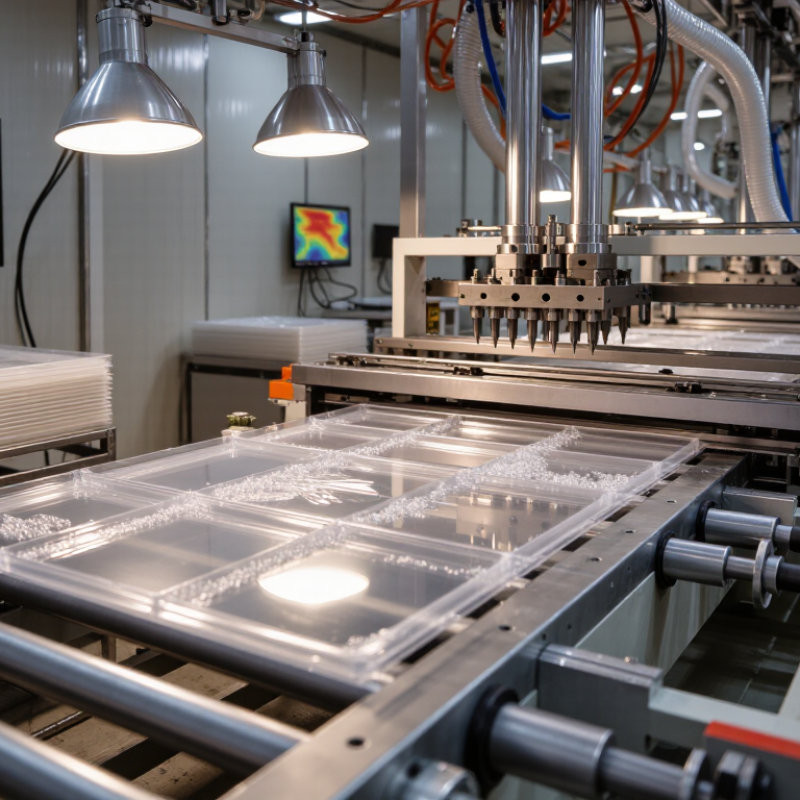
Thermoformed PETG defects often begin before the sheet reaches the forming station. Moisture is a frequent cause, especially when pellets or regrind absorb humidity during storage. For stable processing, PETG moisture should remain below 0.04% before melting. Even a small increase can create bubbles, silver streaks, surface haze, or weak areas after forming.
Drying conditions need practical control. Operators should verify dryer temperature, residence time, airflow, and dew point instead of trusting a timer alone. A sealed hopper helps prevent dried material from absorbing moisture again. Moisture testing can confirm the result, while visual inspection may reveal only the worst cases.
Drying is not optional.
Contamination creates a different defect pattern. Dust, degraded resin, paper fibers, and unmixed color particles can produce black specks, pinholes, rough surfaces, or inconsistent thickness. Regrind should be screened and stored in clean, closed containers. Melt filters and regular barrel cleaning also reduce carryover from previous production.
A small mistake multiplies.
It is easy to blame the mold when the real problem began in material handling. However, drying below 0.04% does not guarantee perfect parts. Excessive heat, long residence time, poor venting, or uneven sheet heating can still damage PETG.
Process records should connect moisture readings with actual defects, not assumptions. That step is often missed, and the missed evidence makes troubleshooting slower.
Uneven heating is a common cause of warping, thin corners, webbing, and incomplete forming. A sheet may look uniformly warm, yet its center can remain colder than its edges. That hidden difference matters. For example, a 180°C forming temperature with a ±5°C variation creates an 11°C total spread. Material flow then changes across the mould.
The U.S. Department of Energy’s 2022 Manufacturing Energy and Carbon Footprints report identifies process heating as roughly 51% of manufacturing energy use. Thermoforming teams should therefore control heat, not simply add more power. Infrared zones need regular mapping with a calibrated surface thermometer or thermal imaging system. Measure several points, including corners and the sheet center. Record results before production changes.
In practical audits, stable sheets often show fewer local thickness failures. However, ±5°C is a control target, not a universal guarantee. Polymer type, sheet thickness, moisture, and dwell time also influence forming behavior. SPE Thermoforming Division technical proceedings repeatedly emphasize process measurement and repeatability. Still, operators sometimes trust heater settings too much. That is a mistake.
Check temperature immediately before forming. Check it again after maintenance. A small sensor error can mislead the entire process. Keep the measured variation within ±5°C, then challenge that limit when defects continue. Surface temperature is only part of the story.
Industrial thermoforming usually operates with a vacuum differential of 0.8–0.95 bar. NIST lists standard atmospheric pressure as 1.01325 bar. Therefore, 0.95 bar already approaches the practical pressure limit. A perfect vacuum is impossible in normal production.
At 0.9 bar, a 0.1 m² panel experiences roughly 9,000 newtons of forming force. That force can expose weak tooling, poor venting, or uneven sheet heating.
Vacuum alone does not guarantee accurate parts. SPE Thermoforming Division technical papers link wall variation to material temperature, draw ratio, vent location, and forming speed. When a sheet stretches deeply, corners become thin first. Webbing may appear near adjoining walls. Trapped air can leave dull patches or incomplete details. Small vent holes matter. Poorly placed vents can delay air removal by fractions of a second.
Plug assist reduces the initial draw before vacuum reaches its peak. It pushes hot material toward deep corners and can improve thickness distribution. Timing remains critical. A plug that arrives too early may create marks. A late plug may add little support.
The plug surface must also match the sheet temperature carefully. One practical calculation helps: 0.8–0.95 bar equals 80–95 kPa, not unlimited pressure. Treat it as a controlled process window.
Review SPE forming guidance, NIST pressure data, and actual thickness maps together. I would not trust machine settings alone. Thermal images often reveal the defect before the finished part does.
What Causes Defects in Thermoformed Products?
Thermoformed parts often fail at corners before flat surfaces show trouble. During forming, heated sheet material stretches around tight radii and deep transitions. The corner can become more than 50% thinner than the original sheet, depending on geometry, temperature, and draw ratio. A sharp corner creates a severe material-distribution problem. It may look acceptable after trimming, yet crack during assembly or service.
Tooling strongly influences this risk. Small radii, excessive depth, and poor draft force plastic into difficult paths. Uneven heating can make one side of the part softer, causing local thinning and webbing. Vacuum timing also matters. If the sheet contacts the tool too early, it may freeze before reaching the intended shape. Experienced process teams inspect wall thickness at corners, ribs, and base transitions rather than checking only the average value. Ultrasonic gauges or sectioned samples can reveal hidden variation.
Larger radii usually improve flow, but they may change the product’s appearance or fit. That trade-off deserves careful review. Plug assists, controlled pre-stretching, and balanced tool temperatures can reduce stress concentrations. Still, these methods cannot rescue fundamentally weak geometry. I have seen parts pass visual inspection and fail after repeated loading. The lesson is uncomfortable: a smooth surface does not prove uniform strength. Design reviews should include measured thickness maps, not assumptions based on CAD geometry alone.
Representative wall-thickness retention through common thermoformed regions. Thickness decreases as material is stretched over deeper features and sharper corners.
In this calculated engineering example, a 1.00 mm starting sheet retains approximately 45% of its thickness at a sharp corner, equivalent to a 55% reduction. Corner radii, draw depth, plug assistance, heating uniformity, and material distribution can significantly change the final result.
Thermoformed PP parts can look accurate when they leave the forming station. However, cooling and trimming often create visible distortion later. Shrinkage commonly reaches 1%–2%, but it is rarely uniform across the part. Thick corners may cool more slowly than thin walls. This difference can pull flanges upward or twist flat surfaces.
Cooling conditions strongly influence the final shape. Uneven mold temperatures, limited airflow, or early demolding can trap residual stress in the sheet. During trimming, a hot part may flex under clamping pressure. The cut edge then returns slightly after release. Small changes matter. A 1% contraction can shift a 500-millimeter panel by about 5 millimeters. That shift may cause gaps, poor stacking, or misaligned holes.
Tips: Measure parts only after they reach room temperature. Record dimensions at several locations, not just one edge. Use consistent cooling time and support the flange during trimming. Check wall thickness near corners with a gauge. If distortion repeats, compare mold temperature maps with the trimming sequence. Do not assume the drawing is the problem. Our process assumptions can be wrong. A practical trial may reveal that the trimming fixture, not the forming cycle, controls the final error. Record each change carefully, because memory is unreliable on a busy production floor.
PETG moisture should stay below 0.04% before melting. Drying is mandatory. Higher moisture may cause bubbles, silver streaks, haze, or weak areas.
Operators should verify temperature, residence time, airflow, and dew point. A timer alone may hide poor drying conditions. Moisture testing provides stronger evidence.
Dried material can absorb humidity from surrounding air. A sealed hopper helps protect it. Open containers can quietly undo the drying process.
Dust, degraded resin, paper fibers, and unmixed color particles may create black specks or pinholes. They can also cause rough surfaces and uneven thickness.
Screen regrind and store it in clean, closed containers. Use melt filters and clean the barrel regularly. Small handling errors can multiply.
No. Excessive heat, long residence time, poor venting, or uneven heating can still create defects. Our assumptions may be wrong.
PP commonly shrinks 1%–2%. Shrinkage may vary across the same part. A 1% change can shift a 500-millimeter panel by about 5 millimeters.
Measure parts after they reach room temperature. Record several locations, including corners and flange areas. One edge is not enough.
Thick corners cool more slowly than thin walls. Uneven mold temperatures, limited airflow, or early demolding may trap stress. Hot parts can flex during clamping.
Support the flange during trimming and use consistent cooling time. Check wall thickness near corners. Compare mold temperature maps with the trimming sequence. Record every change. Memory is unreliable.
Understanding what causes defects in thermoformed products requires examining the entire forming process, from material preparation to final trimming. Moisture and contamination in the sheet can create bubbles, surface marks, or weak areas; for PETG, processing moisture should remain below 0.04%. Uneven heating is another major concern, so sheet temperature variation should be maintained within ±5°C to ensure consistent stretching and forming.
Forming conditions also affect product quality. Industrial vacuum forming typically operates at 0.8–0.95 bar, while improper plug-assist control can lead to uneven material distribution. Tool geometry is equally important because sharp corners may reduce wall thickness by more than 50%, increasing the risk of failure. Finally, cooling and trimming must be carefully managed, since PP products commonly experience 1%–2% shrinkage. Controlling each factor helps improve dimensional accuracy, wall uniformity, appearance, and overall product reliability.

Switara Packing